![]()
1. Overview
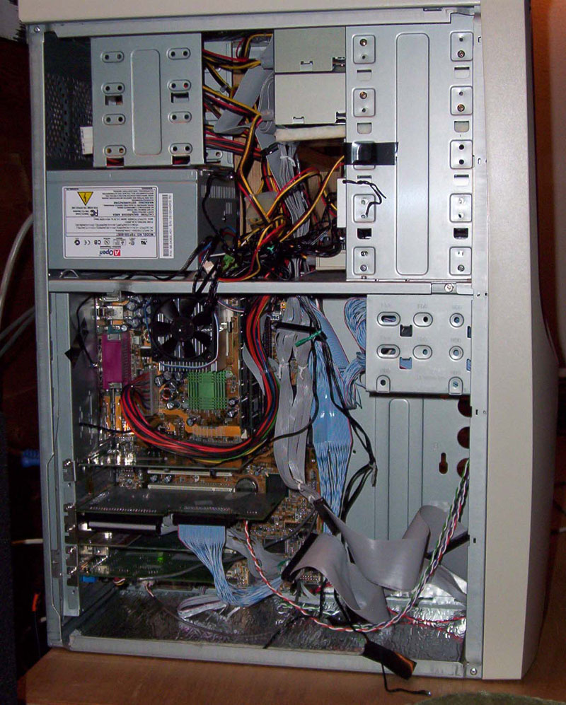
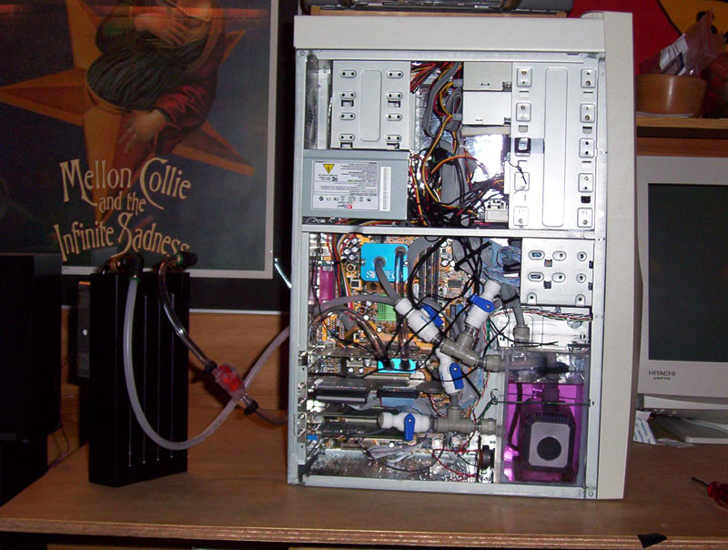
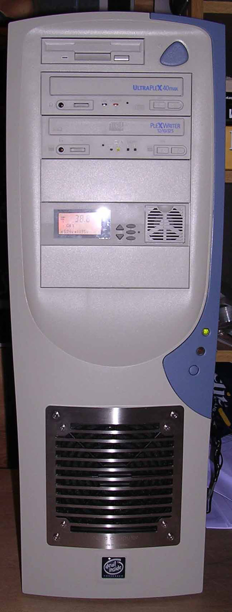
This is a little about my watercooling project. The main reason to use watercooling in my PC is to get a quiet machine. As you can see from the hardware I really don't need the extreme cooling, but as I said it's for the noise. This is my first watercooling so this is no expert description.
My original hardware:
| Intel Pentium III 1000MHz | |
| Aopen HQ08 | |
| ATI Radeon 64MB VIVO DDR | |
| 512MB RAM | |
| ASUS CUSL-2 (Motherboard) | |
| Quantum Atlas 10K2 U160 | |
| Adaptec SCSI Card 29160N - Ultra 160 SCSI |
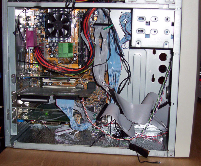
My new hardware (The pics are from the old setup):
| AMD Athlon XP2500@3200 | |
| Aopen HQ08 | |
| ATI Radeon 9800 PRO | |
| Corsair TWINX 512MB RAM (Two matched 256MB) | |
| ABIT NF7 (Motherboard) | |
| Quantum Atlas 10K2 U160 | |
| Adaptec SCSI Card 29160N - Ultra 160 SCSI |
This is some of the stuff I ordered for the watercooling (I ordered everything from www.microplex.no):
| Eheim 1048 waterpump, AC41002 | |
| Swiftech CPU-waterblock, MCW372 | |
| Swiftech GPU-waterblock, MCW40 | |
| Arctic Alumina Thermal Adhesive, AATA5G | |
| AC radiator, "airplex EVO 240", AC31011 | |
| Titan fan, alum., 134m�/time, 30dB(A), TFDA12025M12C | |
| Zalman fan speed controller, FANMATE1 | |
| Redline Oil Water Wetter, RLOWW | |
| (and of course tubes and fittings) |
![]()
2. The tank
The first I had to do was to make a watertank. Since I was going to submerge the Eheim 1048 I didn't find a suitable tank that also fitted inside my case. So I went out and bought me some plexi and some silicon. I glued the plexies together with glue before I filled the inside corners with silicon. Then I drilled holes to the fittings and other things that needed to get out of the tank. I used the same procedure for the fittings, glue then silicon on the inside. The pump i glued on to some foam-like bits that I cut to fit and then glued it all to the bottom of the tank. My plan was to use a packing on the top lid and then screw it on, but I couldn't get it watertight. So I used silicon and screwed it on, at least it is watertight and it isn't that many times you have to open it again.
Tips:
| Remember to have an outlet in the top of the tank to let the air out when filling the system with water. It can also be an idea to have the filling inlet in the top of the tank so that the water going in goes in to the air in the tank (this is only for filling). To have both in the top is my first mistake. | |
| The water that comes from the system should come into the tank under the water to reduse the noise of the waterfall. An idea could be to mount the fitting over the water and then use a tube inside the tank to lead the water down under the water in the tank, this way you can disconnect the tube with water inside the tank and without the water flowing out. My second mistake, well I don't really call it a mistake but a chance of doing better. | |
| Remember to test the tank with water in it for some time to find leaks. It's also a very smart thing to test with all components connected. |
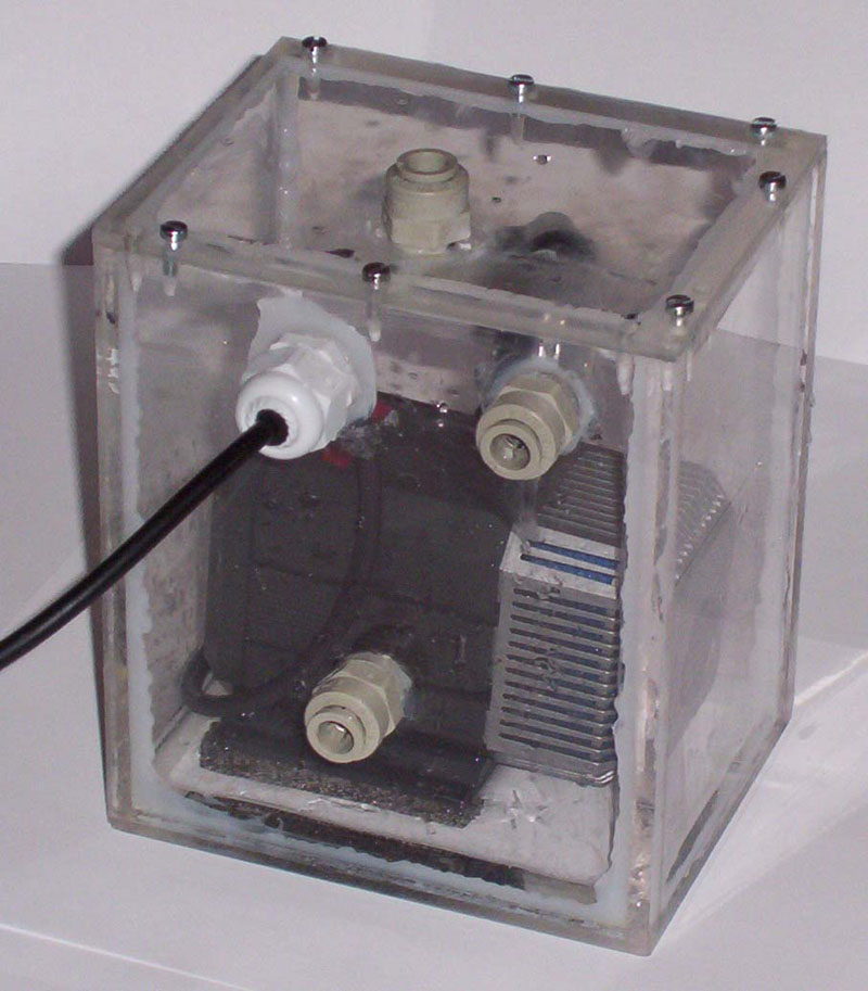
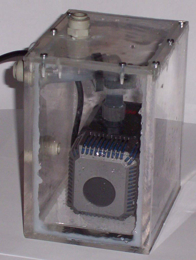
Here you can see the tank in it's full ...ehmmm... glory.
![]()
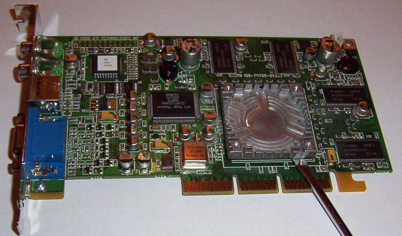
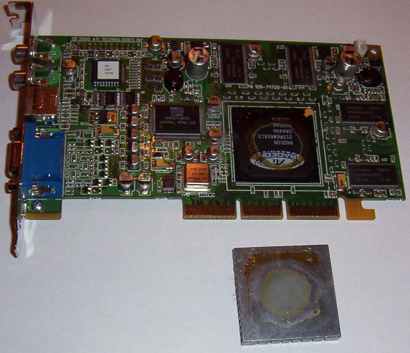
3. The GPU
Since the ATI Radeon 64MB VIVO DDR doesn't have any mounting holes/brackets on the original heatsink and this heatsink is/was glued to the chip I had to rip it off and then glue the MCW40 to the chip. This is probably the most risky thing I did during the project (other than filling the computer with water). I read alot about this matter before I did it so I was prepered. Some tips was to heat the heatsink with a hair drier and then use a screwdriver to force the heatsink off, other was to put the card in the freezer for about an hour and then use the screwdriver. What most said was that there was a chance that the chip would follow the heatsink or be destroyed. Many others experienced that when the heatsink finally got loose it came with a bang. Well my experience is better than these, I did not heat it or freeze it, I just used the screwdtiver (actually to check how good it sat) and the heatsink came of right away. It felt like it only hang in some stickery goop, it felt like someone had put a gum under it. After I had scraped off all of the remaining glue on the chip I cleaned it with isopropyl alcohol. Then I glued the MCW40 on the chip using the Arctic Alumina Thermal Adhesive.
Tips:
| Check that the waterblock fits on the card, that it only rests on the chip and that there are room for the tubes without putting presure on any components. | |
| Have EVERYTHING ready before you mix the adhesive. Try simulating the act and be shure that you have all you need within reach. Remember you have only a few minutes (if that long) before there is no turning back, and as it says on Artic Silver's pages "Any components you attach together with Arctic Alumina Thermal Adhesive will stay attached forever." | |
| Otherwise follow the instructions from Artic Silver. |
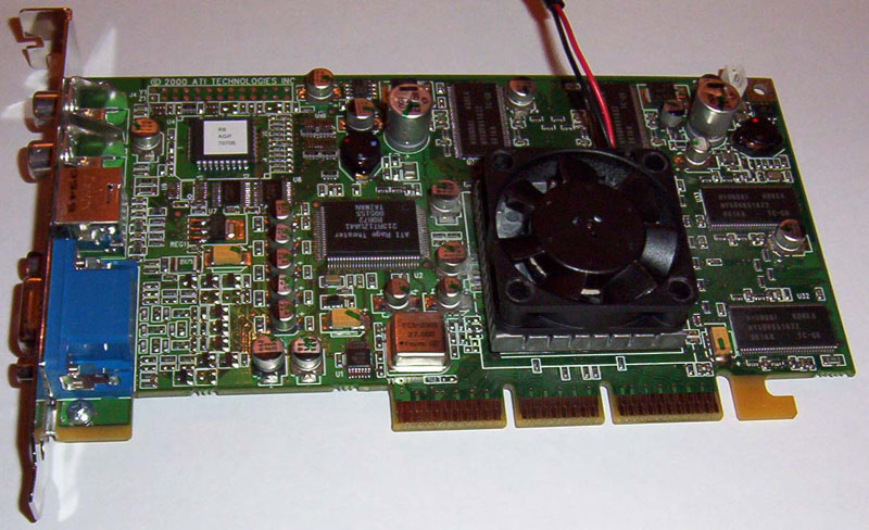
Just a walkthrough on removing the old heatsink...
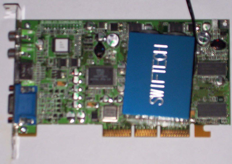
...and positioning of the waterblock...
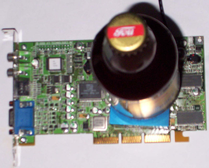
...and the gluing.
![]()
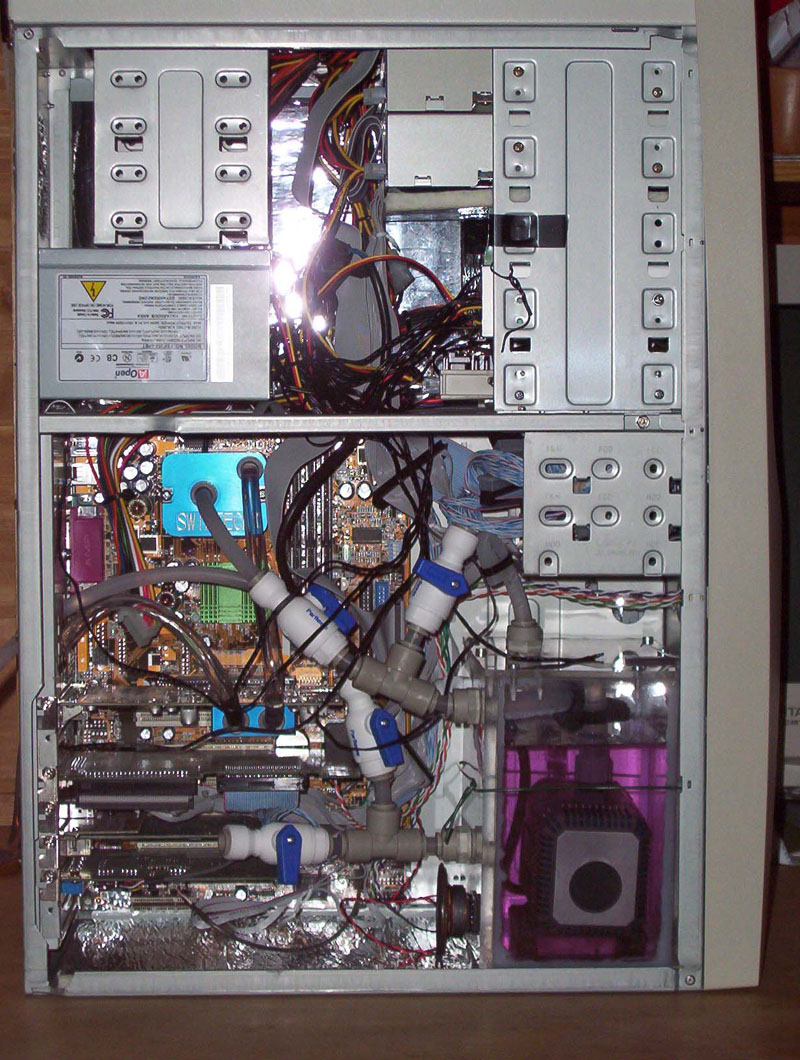
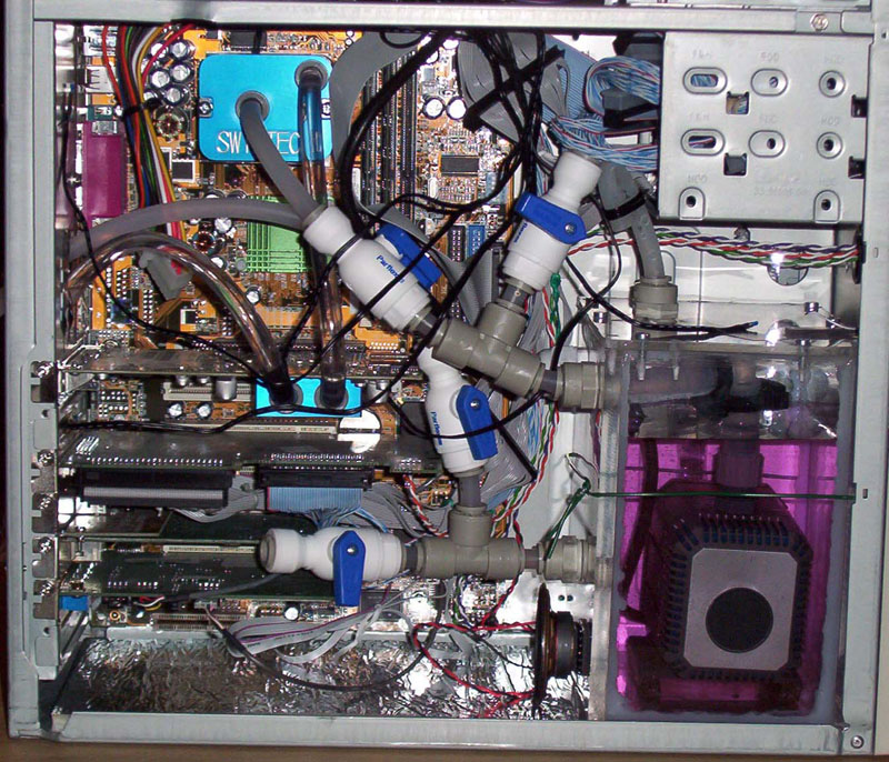
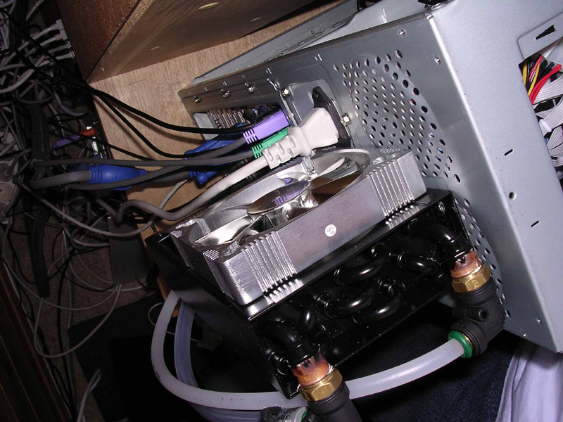
4. The mounting
This was an easy part of the job, the MCW372 is monted just like any CPU heatsink. The graphics card I've allready talked about. The tank was special made for the case so I knew it fitted, all I had to do was to secure it. To do this I put a steel cord around it through some holes in the case, since there is a metal "clamp" usually to hold the LED-wires and this is exactly at the top of the tank, this holds the tank down. As you can see on the pictures I have not yet mounted the radiator as this is something I will do when I also get watercooling on the PSU and that fan goes away.
I monted everything then mesured and cut the tubes (espesially for CPU and GPU) then I dismounted the CPU and graphics card to attach the tubes while I could hold a good grip on the waterblock and not risking any damage to motherboard or graphics card.
When all the tubes where in place it was time to fill up with water, start the pump and get out the air in the system. To do this rock the computer in different directions until the air is out, but don't do as I did when all the air was out, I thought "OK now I'm gonna be sure there's no air" and I turned the computer over so that the pump sucked in air! and I had to start all over again. Well, actually it's not hard, the only things that realy traps air is the waterblocks.
Tips:
| Don't be too eager to turn on the computer, let the water flow for some time and check for leakages. |
Some before pictures...
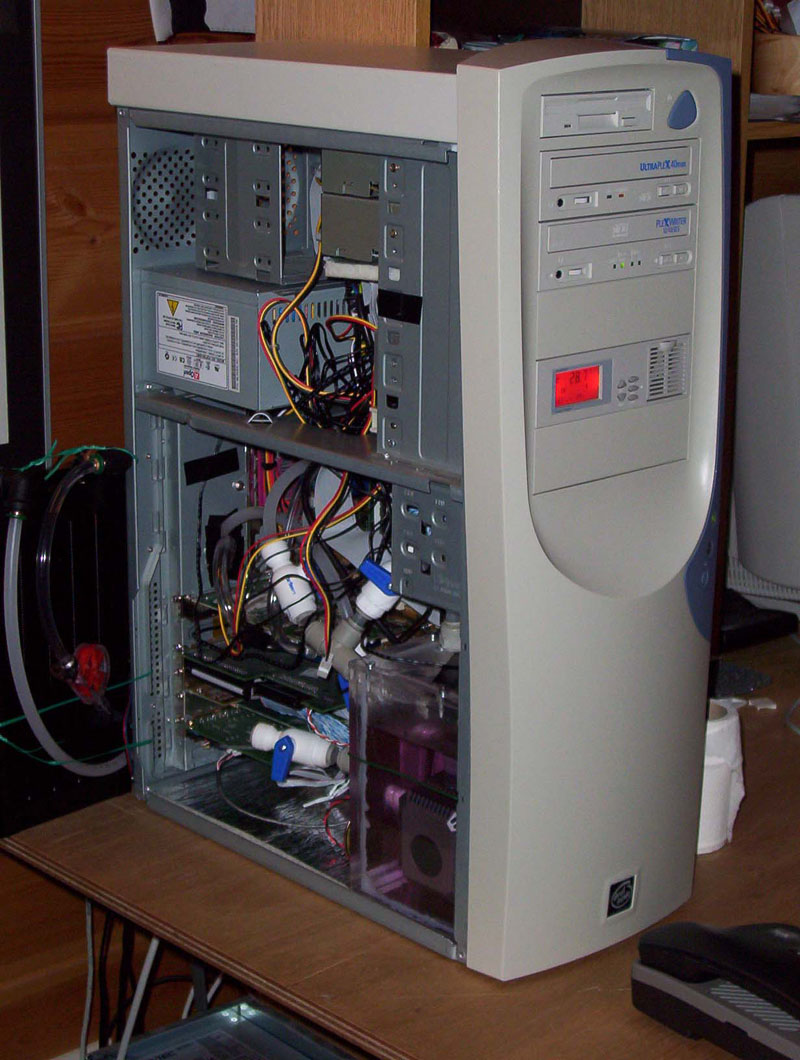
...and some after.
![]()
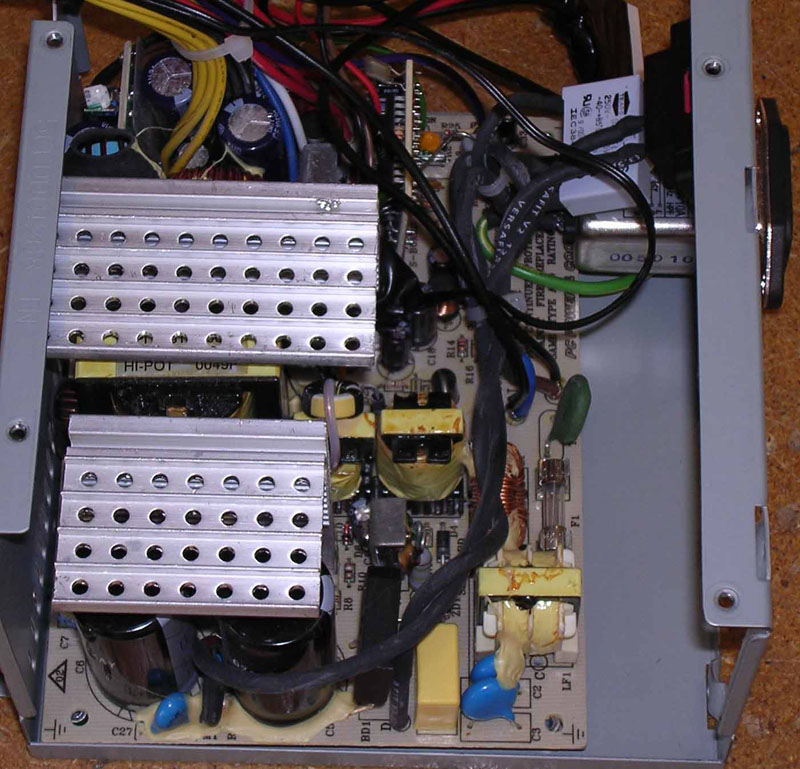
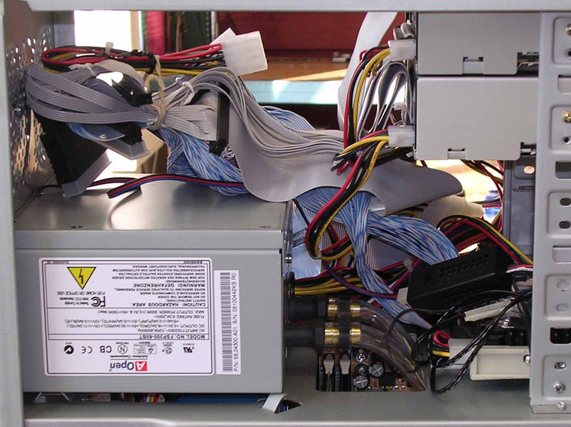
5. The PSU
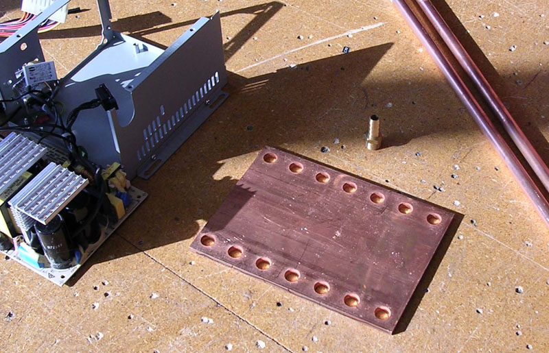
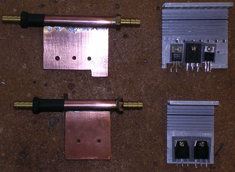
The second stage of my watercooling adventure was the powersupply (PSU). Since I didn't want to pay about 3000 NOK ($400) for a 250W watercooled PSU, I decided to make one out of my standard PSU. The price: 300-400 NOK ($40-55) including that I had to buy 2m of copper pipe and I only used about 20cm.
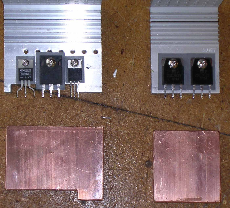
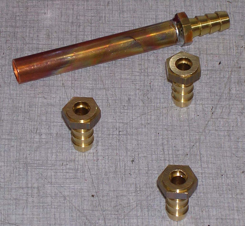
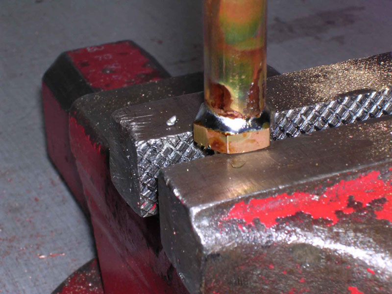
The first I did was to disasemble the PSU and unsolder the transistors (the ones with the big heatsinks on them). Then I cut some copper plates the same sice, drilled holes in them that matched the holes on the original heatsinks. Since I didn't need the full lenght of the tube fitting I cut away some of it so that it wouldn't take to much space inside the PSU. Then I soldered the copper pipe to the fitting. This is something that requiers a great deal of heat, so I used a blowtorch for this. After I had soldered one fitting at both ends on each of the copper pipes I soldered the copper plate onto the pipe the same way. Then it was just to mount the transistors onto the new heatsinks, I used some goop between them. Remember to also use the smal rubber stuff that is between the transistors and the heatsink and the plastic that is arouns the screws THESE AVOID SHORT CIRCUTING. When this was done I soldered the transistors onto the PSU, of course I had cut some holes in the casing for the pipes. Then I put a tube between the the two heatsinks, the link between them inside the PSU. I had to put a parflex tube inside the PVC tube so that the PVC tube would't be squeezed in a sharp bend like that (this is just a temporary solution). THESE AVOID SHORT CIRCUTING
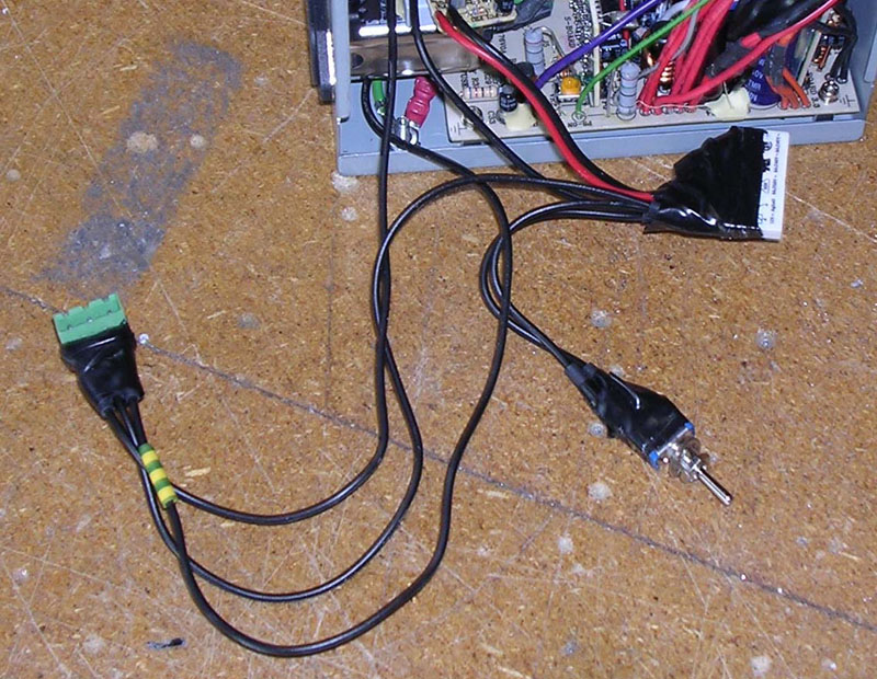
I also made some electrical modifications to the PSU so that the pump would start up automatically when I start the computer. To do this I connected a relay between the pump and the mains from the socket of the PSU. This relay triggers I connected to where the fan was previously connected, because this connectors has some protection so that the fan don't cause noise on the supply to the other components. I also put a switch in parallell with the relay so that I can start the pump without having to start the computer, neat when removing air from the system. And of course I have a connector on the wires to the pump so that I can remove the PSU without having to also remove the pump.
Then I mounted the PSU into the PC and the tubes as they now had to also visit the PSU.
Tips:
| Be shure not to let the new heatsinks touch anything of metal that the old ones did. That could lead to short circuiting. This is including connecting the two copper pipes on the heatsinks. | |
| When soldering the copper you should know that when component number two (and three) is soldered onto the copper pipe, the first (and second) will loosen and fall off if you don't secure it (not with your hand, because of the high temperature). |

Pictures from before and of the ingredients.
Pictures from before inside and of the new copper blocks.

Soldering.
Finished blocks and the electrical modifications.
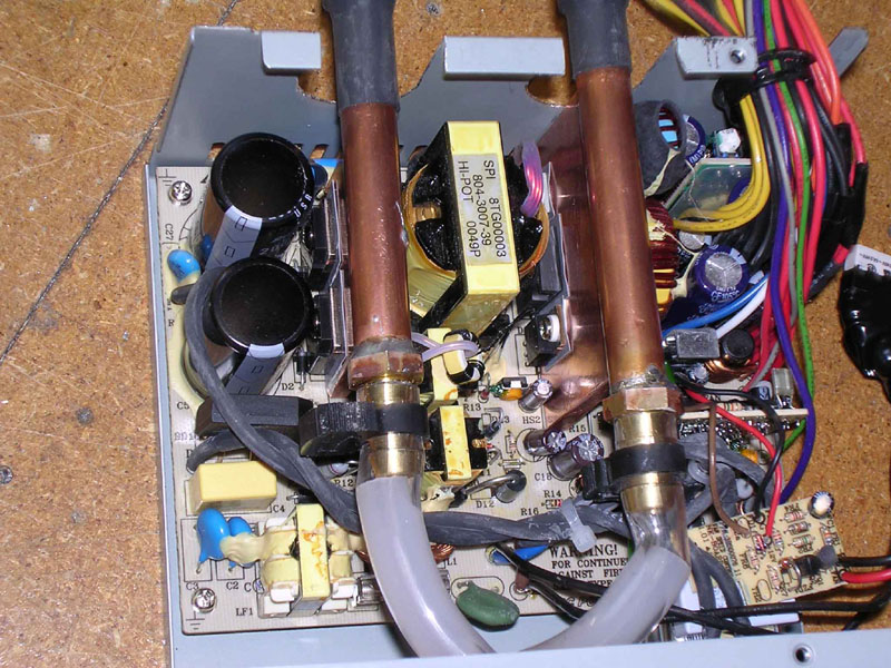

Some pictures of the finished powersupply.
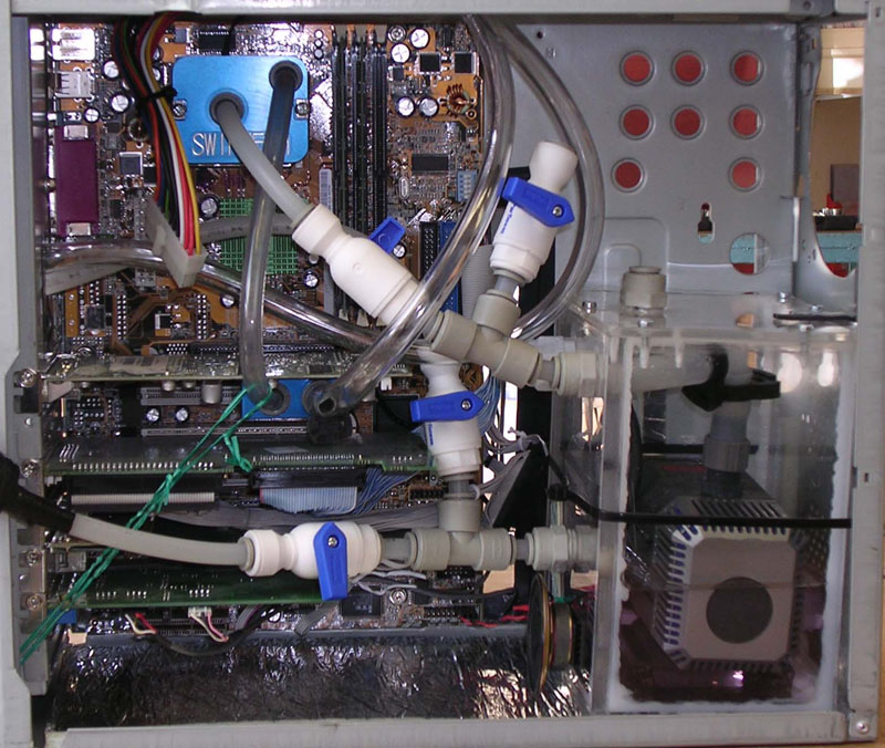
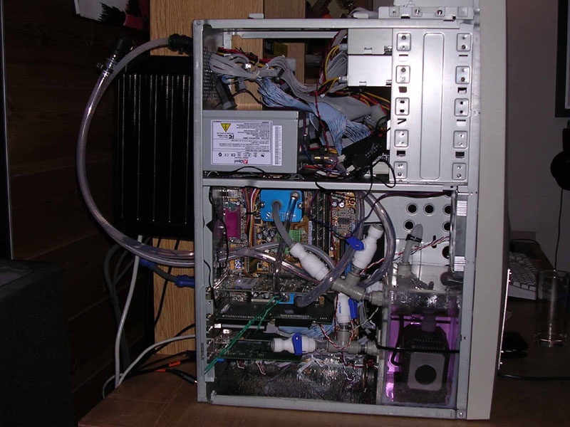
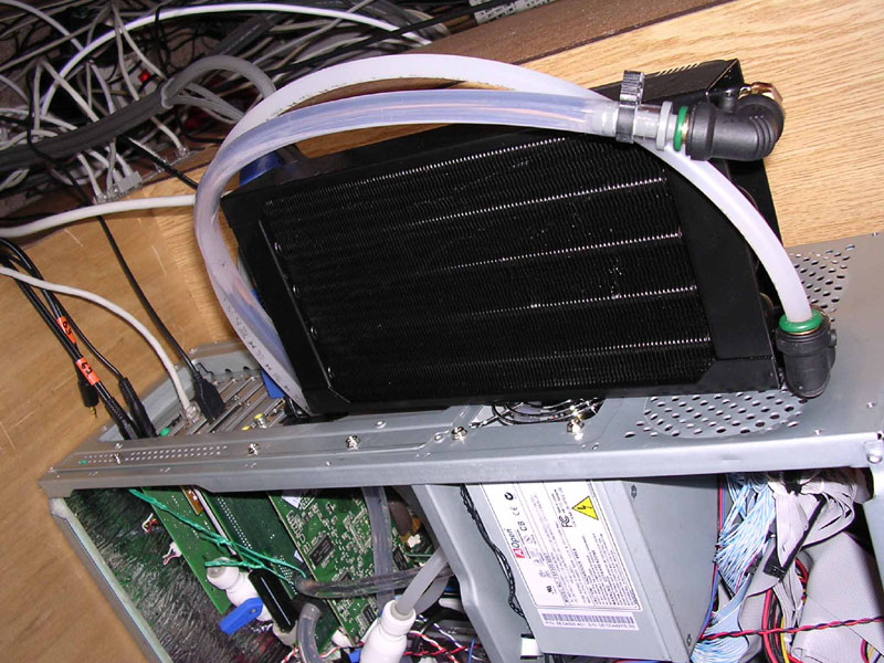
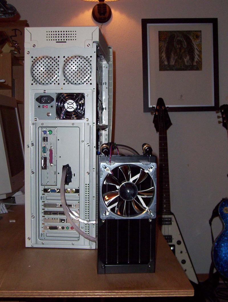
Some pictures of the finished PC with the radiator mounted on the back of the case.